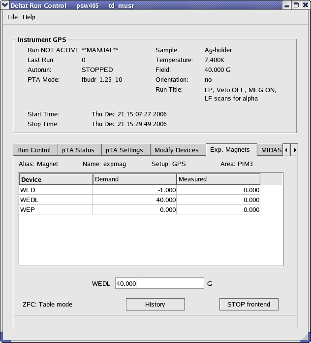
Example of the dialog window to modify the field of a device. By clicking on the desired magnet in the table, the new demand value can be entered in the text-editing field.
Exp. Magnets is selected a list of the available magnets will appear on a table. By clicking one of the magnets, its "demand" value can be changed in the text-editing field. Depending on the reaction speed of the magnet power supply, the measured value will eventually reflect the new "demanded" value.
Example of the dialog window to modify the field of a device. By clicking on the desired magnet in the table, the new demand value can be entered in the text-editing field.
If the tab Modify Devices is selected a list of the available devices will appear. The Temperature Controller device can be selected and a button Modify will appear.
By hitting the button Modify, a first dialog appears giving the possibility either to change the setpoint(s) (Modify Temperature) or modify the setup (i.e. when changing holder or cryostat; Modify Setup). Also the user has the possibility to put the controller in the Control or Monitor mode.
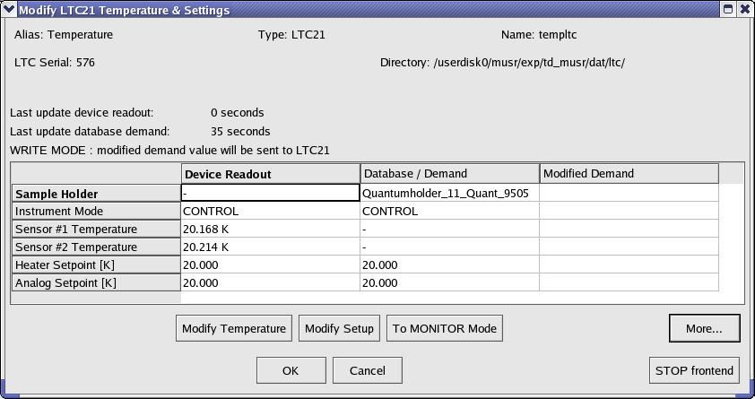
First dialog to modify the temperature setpoints(s) or setup of the LTC21 temperature controller.
OK.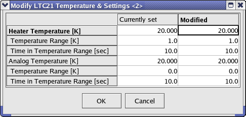
Second dialog to modify the temperature setpoints(s).
Modify Setup has to be pressed. A "wizard" dialog will appear with a drop-down list on the first page giving the possibility to choose the new sample stick.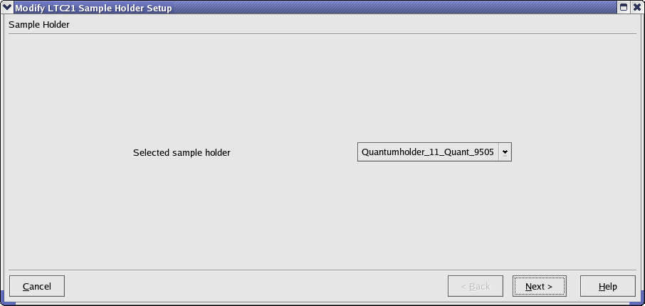
Dialog to choose the new sample stick.
Next, the second page will appear where the configuration can be choosen (1 or 2-loop mode, etc...). By choosing the corrected entry, the setup can be finished by hitting the button Apply & Exit.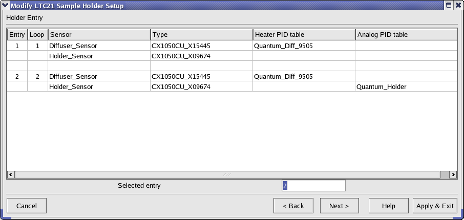
Dialog to choose the configuration for the new sample stick.
If the tab Modify Devices is selected a list of the available devices will appear. The Temperature Controller device can be selected and a button Modify will appear.
By hitting the button Modify, a first dialog appears giving the possibility either to change the setpoint(s) (Modify Temperature) or modify the setup (i.e. when changing cryostat; Modify Setup). Also the user has the possibility to put the controller in the Control or Monitor mode. This can be done either by switching OFF the heater loops (Monitor/Control button) or by interrupting the heater loop wires using the HECTOR module (button Switch Output Control ON/OFF).
First dialog to modify the temperature setpoints(s) or setup of the LTC21 temperature controller.
OK.
Second dialog to modify the temperature setpoints(s).
Modify Setup has to be pressed. A "wizard" dialog will appear with a drop-down list on the first page giving the possibility to choose the new sample stick.
Dialog to choose the new sample stick.
Next, the second page will appear where the configuration can be choosen (1 or 2-loop mode, etc...). By choosing the corrected entry, the setup can be finished by hitting the button Apply & Exit.
Dialog to choose the configuration for the new sample stick.
If the tab Modify Devices is selected a list of the available devices will appear. A device can be selected and, if a modification is indeed allowed, a button Modify will appear.
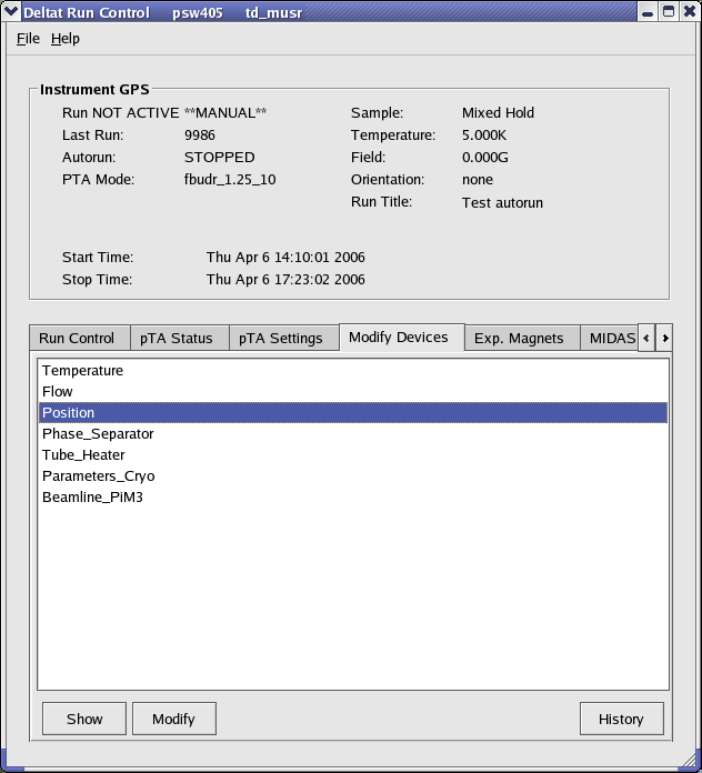
Example of a device for which a modification is allowed.
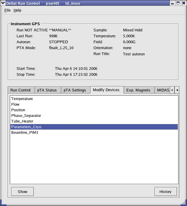
Example of a device for which no modification is allowed. Note that the Modify button is not available.
Modify, a dialog appears containing a table with the different parameters available for the choosen device. By clicking one of the parameters, its "demand" value can be changed in the text-editing field. Depending on the reaction speed of the device and the reading of the related front-end, the measured value will eventually reflect the new "demanded" value.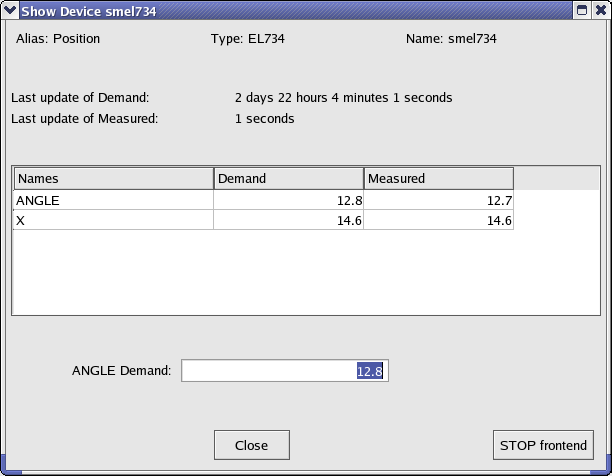
Example of the dialog window to modify parameters of a device. By clicking on the desired parameter in the table, the new demand value can be entered in the text-editing field.
STOP Frontend does not usually appear when normal user-operation is in progress.  1.5.1-p1