This section describes how to setup the different parameters of the CFDs used with the TDC Electronics:
- Principles of the CFD circuit
- Modifying CFD Parameters
- Blocking Mode
- Threshold
- Delay
- Automatic Walk-Adjust
- Width
Principles of the CFD circuit
In a Leading Edge Triggering discriminator, when the input signal has reached the given threshold, an output signal is produced. If the input signal can significantly vary in amplitude (like in our large detectors) and as the rise time from scintillator signals is independent of the signal amplitude, a time shift (so-called Walk) can appear even for simultaneous input signals. This problem is overcome by using a so called Constant Fraction Discriminator (CFD).
In a CFD, the unipolar input signal is turned into a bipolar signal by an appropriate electronic chain. This is done by splitting the input signal with different ratio. One of the signal experiences a certain delay and gets inverted, while the other gets attenuated. Finally both signals are again added to form the CFD bipolar signal. If the delay is choosen so that the zero-crossing occurs when the original signal has its maximum (or better say its minimum), the output signal of the CFD will be independent of the amplitude of the input signal and therefore is not influenced by the input pulse height, i.e. the walk will be strongly reduced .
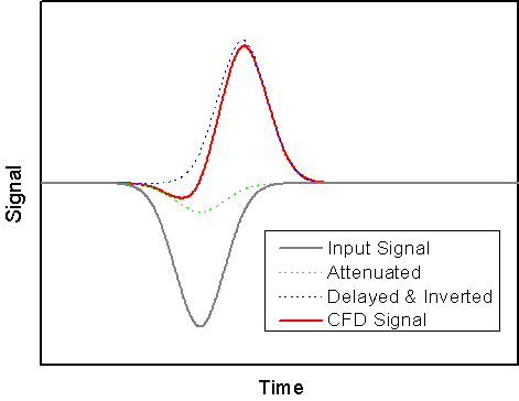
Principle of a CFD discriminator. The input signal is plit with one brach beeing inverted and the other beeing inverted and delayed. The CFD signal is the sum of the two branches and the CFD output signal will appear at the zero crossing of the CFD signal. For simplification, a Gaussian pulse are assumed.
Hence the main parameters to set for the CFD are: the Threshold, the Delay, the "Walk-Adjust" (i.e. the DC level of the internally attenuated signal to be sure that input signals with different amplitudes are transformed in CFD signals crossing at zero). Note that the CFD950 is equipped with an automatic adjustment of the walk (Automatic Walk-Adjust -- See Section Automatic Walk-Adjust).
Modifying CFD Parameters
Modifying parameters through the command line
- login into the backend computer as root
- start the "Midas Slow Control Bus" application invoking:
/usr/local/midas/msc -d mscbNNN, whereNNNrepresents the number of your mscb submaster - enter the corresponding password
- invoke the command
scanto find the different mscb nodes - identify the node(s) corresponding to your CFD(s)
- connect to your CFD(s) using the commmand
add XX, whereXXcorrespond to the node address of the corresponding CFD - list all the variables using the commmand
read - modify the variable that you need.
For example to put the CFD in Blocking Mode (see Section Blocking Mode) the variable 44 ("WIDTH_BU") should be set to 65535:
write 44 65535 - secure your changes in the flash memory:
flash - reboot the adressed node:
reboot - the setup can be dumped into an XML file using the command
save FILENAME.xml. Keep in mind that this also includes the address of the node when loading the file onto a new CFD module (load FILENAME.xml)
Modifying parameters with the GUI deltat
The CFD parameters can also be set through the GUI deltat.
Be sure to start deltat with the special flag.
- on the tab
Modify Deviceschoose the entry which corresponds to the CFD(s) (for exampleVME_CFD) - choose the option
Modify - modify the variable that you need.
For example to put the CFD in Blocking Mode (see Section Blocking Mode), click on the entrycfdN_Width_B_Uand write the value 65535 in the input field. - at this point, you will be asked whether you want to perform a flash & reboot. You can either perform this operation at this point or when you are done changing all the parameters for a given CFD. If you have more than one CFD and are changing parameters on them, be sure to perform a flash & reboot for each CFD.
- Be sure to scroll down to change these values for all the CFDs in use.
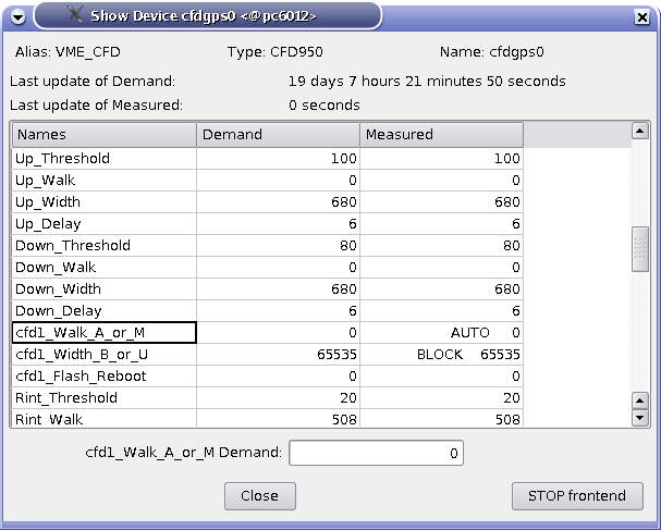
Dialog to change parameters of the CFD. In the present case, the cfdN_Walk_A_or_M has been clicked and can be edited in the input field.
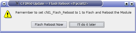
Dialog to perform a flash & reboot of the CFD.
Blocking Mode
The first thing to perform is to set the CFD on blocking mode for the output pulse width (basically to prevent ringing).
To set the CFD on blocking mode, one has to set the MSCB variable 44 ("cfdN_Width_B_U") to the value 65535.
If, for special measurements, the CFD needs to be put on Updating Mode, the entry cfdN_Width_B_U has to be set to 0.
This can be done either from the command line or through the Deltat GUI (see Sections Modifying parameters through the command line and Modifying parameters with the GUI deltat).
Threshold
For each channel, the threshold should be set accordingly. As the threshold scales can slightly vary from channel to channel, it is recommended to perform an active check of the set values. This is performed by splitting the analog signal with the splitter SP950:
- one output channel of the splitter is connected to the input of the CFD. The NIM output of the CFD is sent to the oscilloscope.
- the second output of the splitter is sent to the oscilloscope.
The trigger of the oscilloscope is performed by the NIM output of the CFD. This allows one to observe only the analog signals which are above the effective threshold.
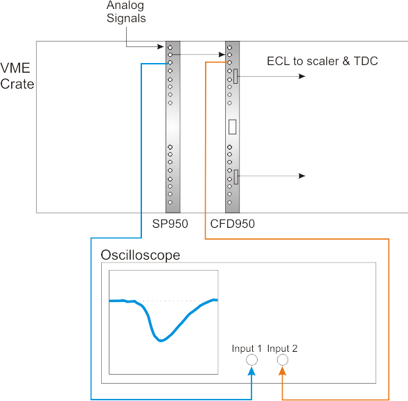
Schematics of the connections to check for the thresholds values. The input 2 is used as trigger.
The threshold values for each channel of the TDC can be modified by setting the MSCB variables 11 to 18 ("THR_CHN", where N is the number of the channel) of the CFD. The value to be set is in millivolts. This can be performed either through the command line (in a similar way as described in the Section Modifying parameters through the command line) or through the GUI deltat (see Sections Modifying parameters through the command line and Modifying parameters with the GUI deltat).
Delay
When equipped with standard delay boards the delay time for the internal non-attenuated inverted signal can be set in 0.5 ns steps. As the CFD board has an internal delay of 1.0 ns, the overall delay can be adjusted by steps from 1.0 to 8.5 ns (i.e. 15 steps).
An approximation of the correct delay is obtained by determining the rise time (  ) of the input signal. Consequently, the delay time is set to:
![\[ t_{delay} = t_{rise} (1-f), \]](form_2.png)
where  is the attenuation factor (in our case 0.2).
The following figure represents different situations with good delay, too long delay and too short delay. The CFD signal can be looked with an oscilloscope connected to the Monitor output of the CFD950 ( see the CFD950 Manual for details).
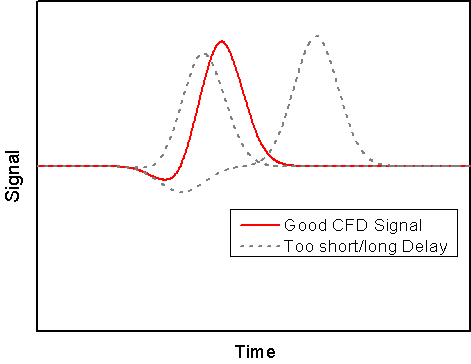
CFD signals with good, too short or too long delay.
The delay values for each channel of the TDC can be modified by setting the MSCB variables 35 to 42 ("DELAY_CN", where N is the number of the channel) of the CFD. The value to be set is between 0 and 15 corresponding to 0.5 ns steps. For example a value of 6 will correspond to a delay of 4 ns (6 steps of 0.5ns plus an internal delay of 1 ns).
The modification of the delay parameter can be performed either through the command line (in a similar way as described in the Section command_line) or through the GUI deltat (see Sections Modifying parameters through the command line and Modifying parameters with the GUI deltat).
Automatic Walk-Adjust
At this point, one can set the CFD on Automatic Walk-Adjust.
The status of the Automatic Walk-Adjust can be modified by setting the MSCB variable 43 ("WALK_A_M"). It should be set to zero for Automatic Walk-Adjust. Normal measurements are performed with Automatic Walk-Adjust.
For Manual Walk-Adjust this variable should be set to 65535.
Again, this can be done either from the command line or through the Deltat GUI (see Sections Modifying parameters through the command line and Modifying parameters with the GUI deltat).
Width
The width of the pulse signals can be set independently for each channel. This is done by setting the MSCB variables 27 to 34 ("WIDTH_CN", where N is the number of the channel) of the CFD. The output pulse width is adjustable on 10-bit from 5ns to 50ns with a non-linear relation for intermediate values.
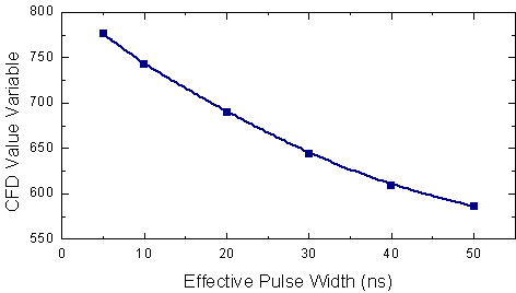
Rough relation between the effective pulse width and the set values of the parameters WIDTH_CN.
The parameters can be changed through the command line or through the GUI deltat (see Sections Modifying parameters through the command line and Modifying parameters with the GUI deltat).