This is a manual for the low energy muon spin rotation experiment ( ). In this manual a detailed description of a sample change with all the necessary preparations will be explained. An inexperienced user should anyhow ask a local collaborator from the group for assistance.
The preparation of a sample change starts already two days in advance of the actual sample change, since the sample has to be glued on the sample plate and should dry at least one day before introducing it into the Ultra High Vacuum (UHV) system of the apparatus.
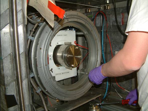
When touching your sample or any UHV components of the apparatus always wear UHV gloves.
In the following, the different steps of a sample change will be explained in detail.
The sample can either be glued or clamped to the sample plate. Only relatively large circular samples can be clamped. Furthermore the heat contact from the sample plate to the sample is better for glued samples. If you anyhow wish to clamp the sample please contact your local contact from the group.
The next figure gives an impression of the effect of different glues.
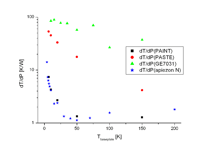
heat resistance of different glues: silverpaint or apiezon N are OK
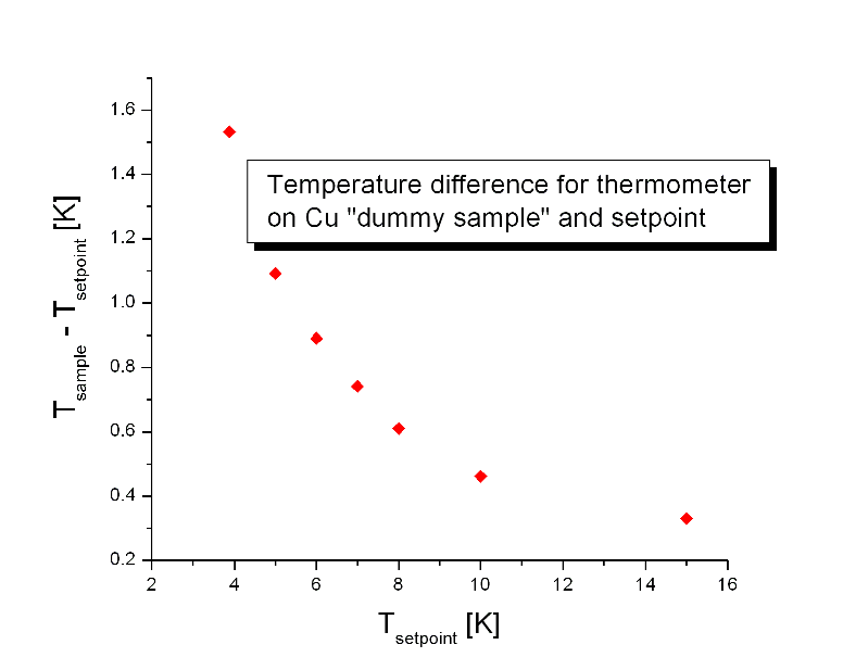
Nevertheless, be aware of the fact that the heatload on a 20*20 mm sample is of order of 0.1 W, resulting in a temperature difference between setpoint as shown in the next figure. Note that for shiny samples this effect is much smaller.
In the following the gluing procedure is described.
-
Take a UHV clean sample plate and orient it as it is mounted in the cryostat, i.e. the High Voltage (HV) connection is pointing to the top right (14:00) (this is true for the Conti1 cryostat).
-
The centre of the
 beamspot is not always in the centre of the sample plate, e.g., in 2005 the beamspot was shifted to the top by about 2mm. If you have a small sample (<2cm) please ask for the actual beamspot position.
-
Glue your sample to the desired position on the sample plate by using silver paint. Use only very little silver paint (a few little droplets are sufficient). Alternatively, you may use apiezon N grease, but be aware of that this is not a glue. Fasten the sample additionally with a very tiny drop of silverpaint, which then also serves as electrical contact.
-
Connect your sample surface with the sample plate electrically by using a little bit of silver paint. If you have a mosaic as a sample, connect all individual pieces to the sample plate.
-
Check the electric connection between the sample surface and the sample plate. (Attention: Use a soft contact when touching the surface of your film, e.g., tin-solder.)
-
Let the sample dry for at least two hours (you might use a lamp to warm it). After this you can put it to the desiccator. Do not stop the pump during the whole drying procedure, so that the solvent is pumped the whole time.
-
Let it dry for at least one day before introducing it to the UHV apparatus.
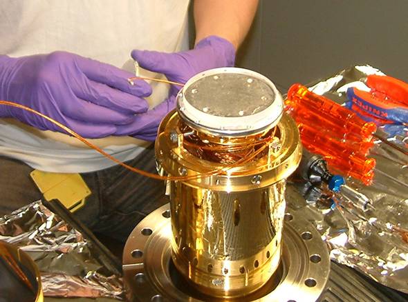
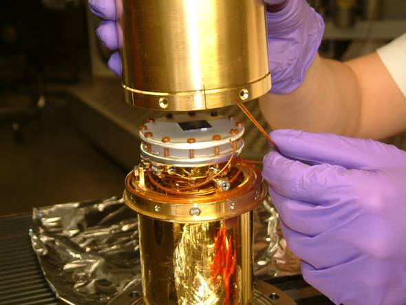
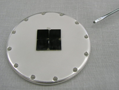
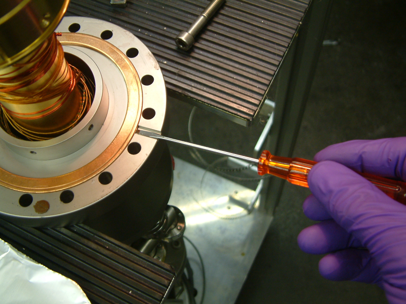
The photo is showing a mosaic sample which is mounted 2mm of centre with the individual piece electrically connected to the sample plate. The screwdriver marks the position of the HV connection.
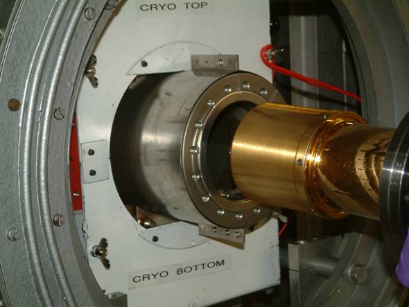
Before the UHV sample chamber can be opened for a sample change, the cryostat has to be warmed up to room temperature. Please follow the instructions carefully. The warming-up procedure takes about 1.5 hours.
-
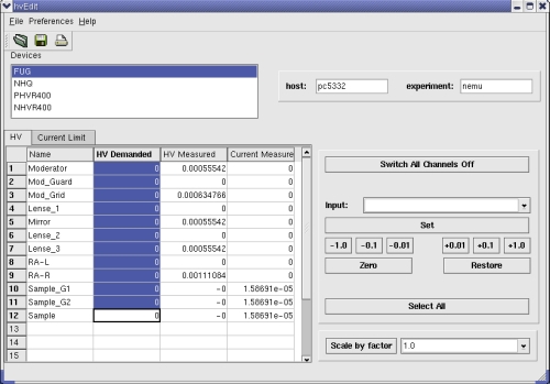
Ramp down the High Voltages (HV) of the transport system and the sample. To do this, open the HV-Edit GUI, select all transport elements and sample voltages and press the zero button.
-
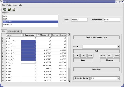
Ramp down the HV of the positron detectors. To do this, open the HV-Edit GUI, select positron detectors and press the zero button.
-
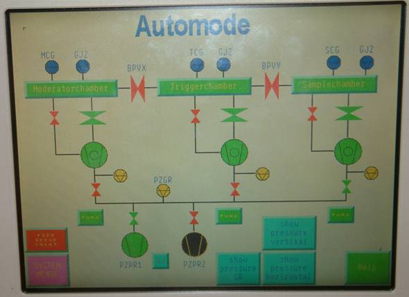
Close the valve BPVY between trigger and sample chamber by clicking the valve in the lemvac GUI. The symbol for the valve should switch to a red colour (closed).
-
Heat up the sample cryostat:
-
Set the temperature of the sample cryostat to 300K (280 K when the sample has been glued with apiezon grease).
-
Stop He pump by pulling out the power plug.
-
Immediately open the bypass valve between the cryo outgas line and the He recovery.
-
Wait until 200K is reached at the sample plate.
-
Vent the sample chamber with nitrogen gas:
-
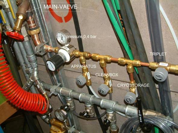
Open the valve from the nitrogen gas supply line to the apparatus at the backside wall of the area (do not touch the pressure reducing valve).
If the valve is opened completely you should hear the opening of the overpressure valves in the nitrogen system.
-
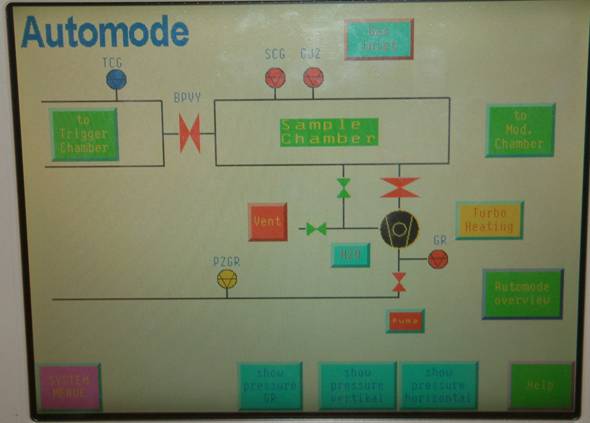
From the vacuum overview switch to the sample chamber view by pressing the sample chamber on the touch screen of the vacuum control.
-
Press the vent button and acknowledge by pressing the red yes button. Now the sample chamber will be vented. The pressure in the sample chamber now should rise to >1000 bar.
-
Wait at least another 45 min until all parts of the cryostat are warm.
-
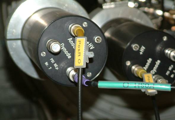
Disconnect all signal and HV cables from the photomultiplier tubes of the positron detectors.
-
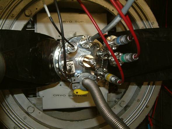
Disconnect all temperature control and HV cables from sample cryostat.
-
Remove the transfer line from the cryostat and immediately put the blind plug instead. Remove the transfer line from the dewar and let it dry before next usage.
-
Close the bypass valve to the He recovery and disconnect the pumping tube from the cryostat. Put blind flanges to protect the tube sealings.
-
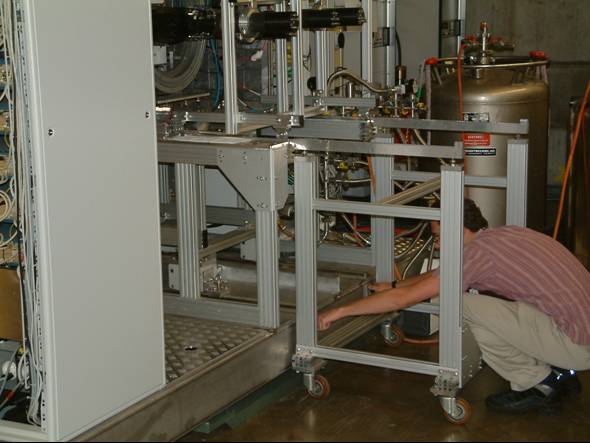
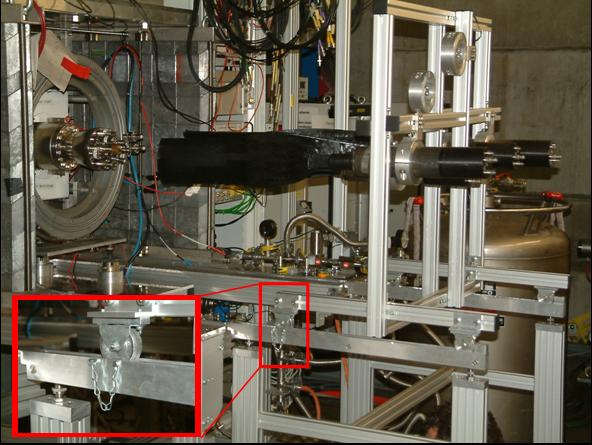
Fix the movable storage wagon for the positron detector to the apparatus by using the knurled screws at the front side (bottom) of the apparatus.
-
Slowly pull the trolley with the positron detectors onto the wagon. It is important to frequently check that the positron paddles are free to move. Fix the wagon on the trolley. Unscrew the wagon from the apparatus and carefully move it aside.
-
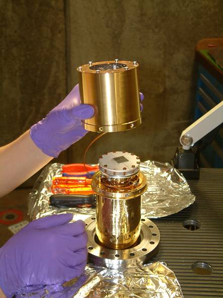
Remove the cryostat from the apparatus by opening the 100CF flange (Attention: Try not to touch the tube walls with the cryostat.).
-
Put the cryostat with the cooling shield to the top onto the movable cryostat trolley.
-
Immediately close the vacuum tube with a 100CF blind flange (four screws are sufficient, you can use an old metal sealing).
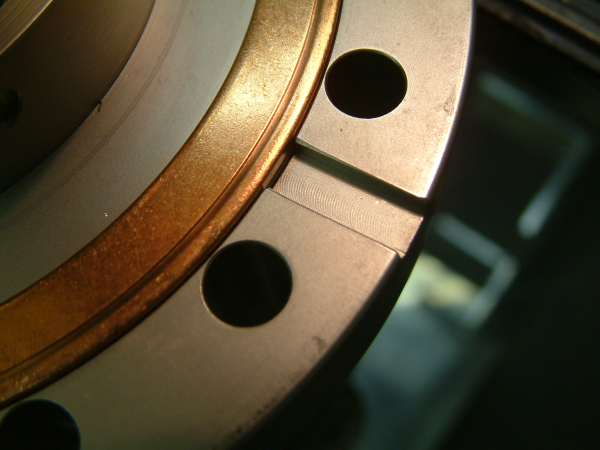
In very rare cases (in particular if the preceeding user has tightened the screws with too much torque) the metal sealing will not come loose from one the flense. In that case some trick has to be applied: Note that the flense has a special groove for this purpose:
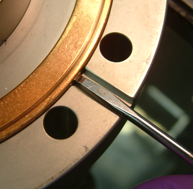
Gently insert a small screwdriver into this groove, under the metal sealing. DO NOT TRY TO PUSH. Under the metal sealing is the so-called knife. If you damage the knife with a scratch, there will be no vacuum any more and THUS END OF EXPERIMENT. Turn the srewdriver or use it very gently as a crawbar.
TURN SREWDRIVER, DO NOT PUSH
Working on the sample cryostat is a very delicate matter where a few rules have to be obeyed:
- Always wear UHV gloves
- Try not to make scratches, since they will produce HV problems
- Take care that the earth grid at the entrance of the cooling shield is not destroyed. Especially do not touch it.
Please follow carefully the following steps to mount a new sample (together with the sample plate) to the cryostat. If an experienced user is available, please ask for assistance for the sample change. All tools that you will need are in the cupboard on the backside of the area.
-
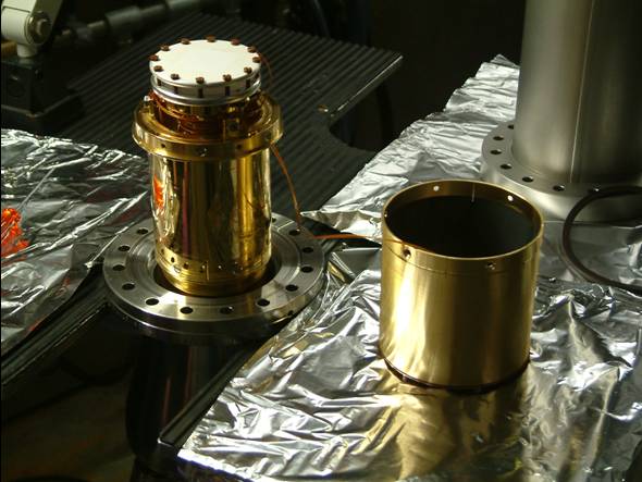
To remove the cooling shield, first unscrew all the hexagon socket countersunk flat head screws and second remove the shield carefully. The guard rings and their HV cables are connected to the shield. Therefore it is necessary to rotate the shield counter clockwise when removing it from the cryostat. Do not remove the HV cables for the guard rings.
-
Put the shield aside.
-
Pull out carefully the HV plug from the sample plate.
-
Unscrew the brown vespel screws by using the appropriate screw driver (to small or to big screw drivers will break the head of the screw).
-
Remove the old sample plate from the sapphire. This might need some force due to the sticking of the indium foil between sapphire and sample plate.
-
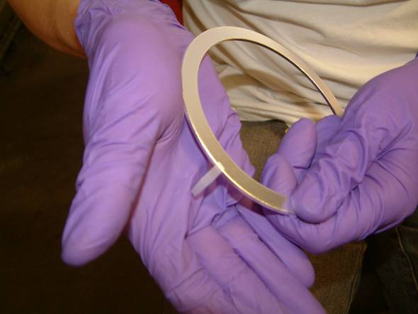
If no indium foil sticks to the backside of the new sample plate, put a new indium foil (diameter 50mm) on the sapphire plate. It is essential, that the foil stays exactly centred on the sapphire and that no parts of the foil looking out from the sapphire (this might cause HV problems).
-
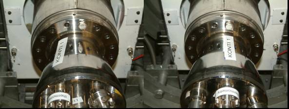
Put the new sample plate onto the sapphire that the HV connection is at the desired position. The top of the cryostat is marked by the upper edge of the "KONTI 1" sticker. The HV connection should point to 14:00 (for the Konti1 cryostat). Make sure that no Indium foil is looking out between sapphire and sample plate.
-
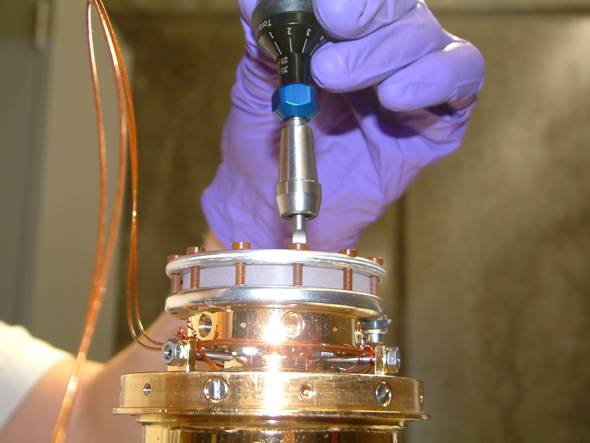
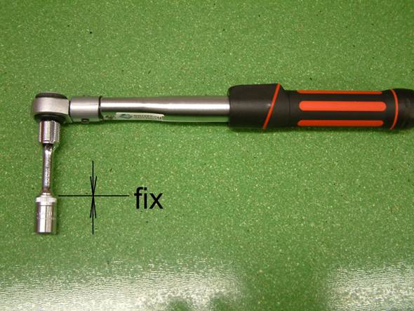
Screw very lightly the brown vespel screws into the sample plate. Fisrt do this with a screwdriver that fits the vespel screws and holding the metal part of the screw driver as shown in the next figure.
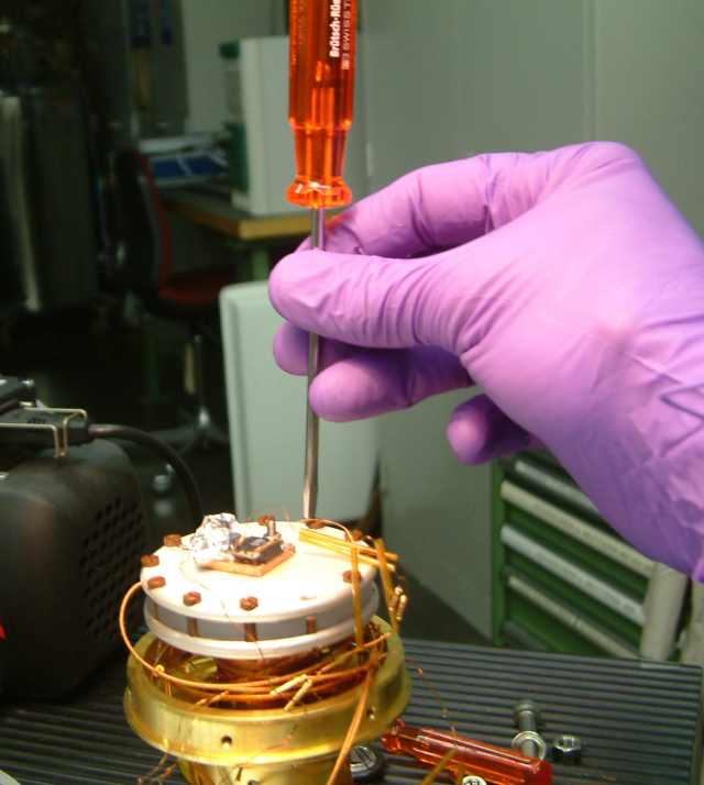
Hold the srewdriver at the metal part so that you CANNOT excert force
Next use the fixed torque srew driver. Make several round trip with increasing force to tight the screws. Go on until all screws are fixed with the same torque. In case a screw is broken, removed with a flat nose pliers. Clean spare vespel screw can be found in the cupboard in the area.
-
Push the HV plug into the sample plate until the metal plug is completely within the plate.
-
Check the electric connection between the outer HV plug and the sample plate with the help of a multimeter.
-
Finally mount again the cooling shield. Rotate slightly the shield counter clockwise to put the HV cables of the guard rings in place; take care that the cables (with have the temperature of the shield) do not touch the cold-finger sample assembly. Fix again the metallic hexagon socket screws.
-
Check that the valve to nitrogen gas supply line at the backside wall of the area is still open.
-
Dismount the 100CF blind flange from the vacuum tube.
-
Fix a new 100CF metal sealing at the vacuum tube by using a little scotch tape. Cover not more than 2mm of the outer sealing diameter with the tape.
-
Immediately put the cryostat to the vacuum tube using a new metal sealing. It is enough to first lightly fix the cryostat with two opposite screws to hold the sealing at place. Now it is possible to rotate the cryostat so that the upper edge of the "KONTI 1" sticker is pointing to the top.
-
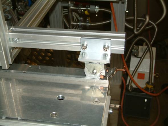
Now gradually screw all the screws one after the other. Make at least three round trips with increasing force to fix the screws. Finally, use the fixed torque wrench (see figure) with 20 Nm to fix the screws tightly.
-
In the sample chamber view of the vacuum control press the vent and afterwards the green AUTOMODE button on the touch screen to stop the vent procedure.
-
In the sample chamber view of the vacuum control press the pump to start the vacuum pumps of the sample chamber.
-
Close the valve to nitrogen gas supply line at the backside wall of the area.
After a few minutes the pumps (first the pre-pump and than the turbo pump) should have started and the pumping station should be in the following situation:
The pumping takes about four hours. Open the valve BPVY between sample chamber and trigger chamber only when a pressure of SC_GJ2  mbar is reached in the sample chamber. This is done by clicking the valve in the lemvac GUI or on the touch screen of the vacuum control. After waiting another 15min you can start to cool down the cryostat. If you do not wait long enough for a good pressure, this will harm the long term stability of the moderator and the residual gas will freeze on top of your sample (which might disturb your measurements).
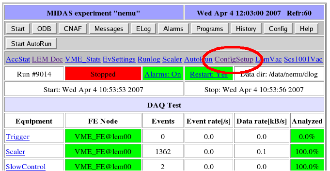
In case there is an exchange of the cryo (e.g. Konit-1 to Konti-2), it is important to update the system in order to work with the proper calibration tables etc. This update is performed the following way:
Select the 'ConfigSetup' link on the main experiment web-page
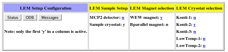
On the "L E M Setup Configuration" page (see picture below), select the mounted cryo.
The configuration is changed the following way
-
Change the active cryo (the one set with a 'y') to 'n'. You have explicitly press the 'set' button, since if you just press the 'return' button nothing will be changed.
-
Now, switch the mounted cryo tag from 'n' to 'y'.
Having selected the new cryo, the system will try to automatically update all the necessary settings. In the ODB message system (running odbedit console or on the web message window), it should look something similar to this
11:07:16 [Sample SC] cryo name = LowTemp-1
11:07:19 [Sample SC] LS340: LowTemp-I: Channel A curve = (ODB=1,LS340=1).
 LS340=1 -> DT-470    ,Standard  ,2,+475.000E+0,1

11:07:22 [Sample SC] LS340: LowTemp-1: Channel B curve = (ODB=1,LS340=1).
 LS340=1 -> DT-470    ,Standard  ,2,+475.000E+0,1

11:07:29 [Sample SC] LS340: LowTemp-1: Channel C1 curve = (ODB=2,LS340=60).
 LS340=60 -> DUMMY 04-03-06 ,D00000    ,2,+7.50000E+0,1

11:07:29 [Sample SC] LS340: LowTemp-1: Controll loop1 settings: A,1,1,1

11:07:35 [Sample SC] LowTemp-1. Zone settings successfully transferred to the LS340.
11:07:35 [Sample SC] successfully switched to LowTemp-1
If you get any warnings, please contact somebody of the LEM group which knows how to interpret them.
For more details see Technical description of the automatic update mechanism for the sample cryo.
While the vacuum of the sample chamber is pumped (after the sample change), there is time to prepare the cryostat for the cooling down procedure, to reinstall the positron detectors for the measurements, and to reset the vacuum interlock system.
-
Put the wagon with the positron detectors in place and fix it to the apparatus by using the knurled screws at the front side (bottom).
-
Carefully push the detector trolley towards the sample chamber until the scintillators touch the backside flange. During the movement of the trolley, check frequently that the scintillators are free to move. Finally, fix the trolley in the end position and remove the storage wagon from the apparatus.
-
Reconnect the signal and HV cables of the positron detectors to the photomultiplier tubes.
-
Reconnect the temperature control and HV cables with the cryostat.
-
Connect the He pumping tube with the cryostat.
-
Close the bypass valve to the He recovery.
-
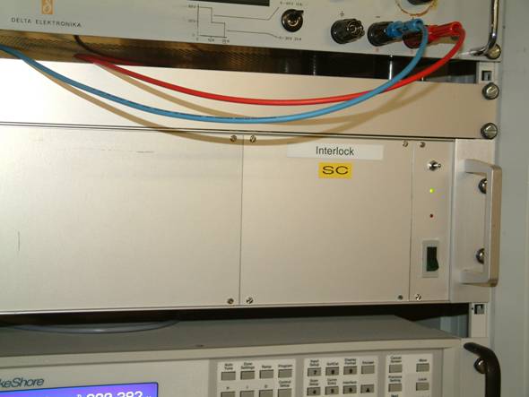
If the vacuum in the sample chamber SC_GJ2
 mbar reset the vacuum interlock for the HV of the sample and the transport system. This is done by using the small switch at the SC interlock unit in the rack right from the sample chamber.
Now the system is ready for starting the cooling and measurement again, if the UHV requirements are fulfilled (see Section Mounting the Cryostat to the UHV Chamber and Pumping ).
In this section the detailed update mechanism concerning the sample cryo settings will be discussed. In the ODB of the nemu experiment there is the entry
/Info/Sample Cryo
The allowed names are given in Update the ODB in case the cryo is exchanged. In sample_scfe.c there is a hotlink to this variable so that if it is changed, it will be transferred to the DD settings in the ODB, namely to /Equipment/SampleCryo/Settings/Devices/Lake340_Sample_0/DD/ODB Names/LakeShore 340 Name. The device driver (LakeShore340.c) hotlinks the DD cryo names and calls a routine called ls340_cryo_name_changed, which is the routine which handles all the necessary changes, which are
-
checks if the given name exists in the ODB DD subtree (see below for the details).
-
read all settings from the cryo specific ODB tree (e.g. DD/Cryos/Konti-I).
-
sets the proper heater resistance.
-
sets the proper sensor types.
-
sets the proper calibration curves.
-
sets the proper zone settings.
WARNING: Two things one should be aware of:
-
The mlogger needs to be restarted if the ODB names are changed, otherwise the history will not be available.
-
If the number of temperature channels are different between cryo settings (hopefully not). The frontend needs to be restarted, since the ODB will change!
For each sample cryo there exists a subtree in the ODB which keeps all the necessary informations. These subtree can be found under
/Equipment/SampleCryo/Settings/Devices/Lake340_Sample_0/DD/Cryos/CryoName
where CryoName is one of the names given above (Update the ODB in case the cryo is exchanged). The cryo subtree is structured as follows:
-
Heater Resistance: holds the resistance of the cryo's heater.
-
Sensor Type: sensor types for the 10 possible channels (for sensor types see the LakeShore340 user manual p.9-33, INTYPE).
-
Calibration Curve: calibration curve number for the 10 possible channels (for details see the LakeShore340 user manual p.9-33 INCRV).
-
Channel: channel name (A, B, C1-C4, D1-D4) for the 10 possible channels.
-
Sensor Name: ODB Names of the 10 possible channels.
-
Zone: 10 Zone settings (see LakeShore340 user manual p.9-42 ZONE).
Generated on Tue May 12 12:11:38 2009 for Low-Energy Muon (LEM) Experiment by
 1.4.7
1.4.7