- The calibration procedure
- tempCalib
- talk_rs232
- Table of the calibration-curves as stored in the Sample Cryo LakeShore336
- Technical Details concerning the calibration procedure
Overview
The calibration procedure
The temperature in the various sample environments of the LEM experiment is measured at the so-called base-plate of the cold finger cryostats. This plate is directly mounted on the cold finger of the Konti- or LowTemp-cryostats. The sample is glued on a second plate, the sample-plate. Between the base-plate and the sample-plate is a sapphire disk of 6 mm thickness for electrical insulation. Indium foils on both sides of the sapphire plate improve the thermal conductance between the metallic plates and the sapphire disk. The sample and the sample-plate "look" directly into the apparatus, that is mainly the ring anodes and the third lens. The ring anodes are at room-temperature. Consequently, there is a considerable heat load on the sample, and a serious temperature difference between the sample and the thermometers at the backside of the base-plate is to be expected.
In order to correct this "miss-measurement" of the temperature, the calibration of the base-plate diodes is carried out "in-situ". A calibrated thermometer is mounted on the spot of the sample and then the cryostat is brought to a number of temperatures at which the temperature of the calibrated thermometer and the voltage (in case of diodes) or resistance (in case of cernox) of the base-plate thermometers is recorded. This recording then forms the bases of the thermometer calibration of the LEM sample-environment. Note that these calibration cannot be used as a 'calibration of the base-plate thermometers', since it depends among others on the mounting of the sample-plate and the heat load from the environment.
In the LEM experiment, the temperature is measured and regulated with a LakeShore 336 controller (LS336). This instrument translates the voltage or resistance measurement into a temperature by interpolation of a breakpoint table. There are 20 "standard" tables and 40 possibilities of user supplied tables. Hence, the thermometer calibration procedure consists of compiling a list of the voltages as function of the temperature of the calibrated thermometer and feeding this list into the LS340.
In order the achieve this goal the following steps have to be taken:
-
Mount a calibrated thermometer on the special sample-plate for temperature calibration. This plate has a few holes with a thread (M3). Wrap the thermometer in Al or In foil to avoid a radiation heatload on the thermometer. Also thermally anchor the leads of the thermometer.
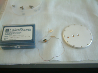 T_calibration sample-plate
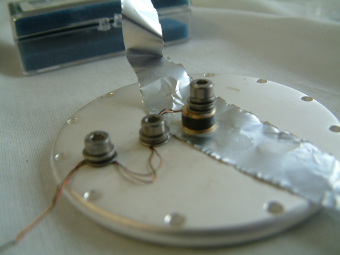 Mounting of thermometer
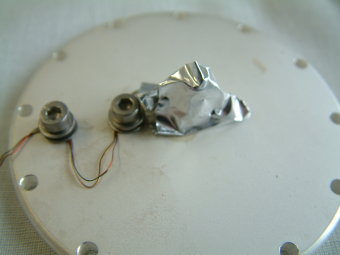 Finished
 - If possible, also mount a heater (e.g. small resistance in TO 220 house). Such a heater enables the determination of the sensitivity to the heat load on the sample plate.
- Mount this special sample-plate in the usual way. Use the wires for the D3 to connect the calibrated thermometer.
- When mounting the cryostat in the apparatus DO NOT connect the high voltage cables. Any high voltage on the sample-plate means the end of the calibrated thermometer which is damned expensive.
- Make sure that the input devices configures on the LS336 and the ODB match (ODB:/Equipment/SampleCryo/Settings/Devices/Lake336_Sample_0/DD/Sensors/).
- Enable the recording of all Raw Voltages (ODB: /Equipment/SampleCryo/Settings/Devices/Lake336_Sample_0/DD/Intern/Read Raw Data).
-
Make sure that the port setting on the LS336 (press "Interface" button) are:
SERIAL
Terminator: CR LF
BPS: 9600
Parity: 8None1
- Gently cool down the cryostat to base temperature.
- Allow for sufficient time to equilibrate all parts of the instrument, e.g. 2 hours.
- Run lemAutoRun with the file T_calibration.lar
- After the run has finished, the file RawVoltageOutput-<CryoName>-<DateTime>.dat contains all data, including header information which are necessary for the calibration software and as a documentation of the setup.
- Run the program tempCalib.
- Run the program talk_rs232 to upload the resulting tables. This should be done on a machine that can connect to the LANTRONICS terminal server to which the LS336 is connected.
- After uploading the new calibration, start "Sample SC", cool the cryostat again and test that it is working properly.
tempCalib
Start the temperature calibration tool using the command
tempCalib 336&
The GUI is organized in three main tabs which are
- the 'Raw Data' tab
- the 'Calibrate' tab
- the 'Plot' tab
which will be exemplified briefly.
Raw Data Tab
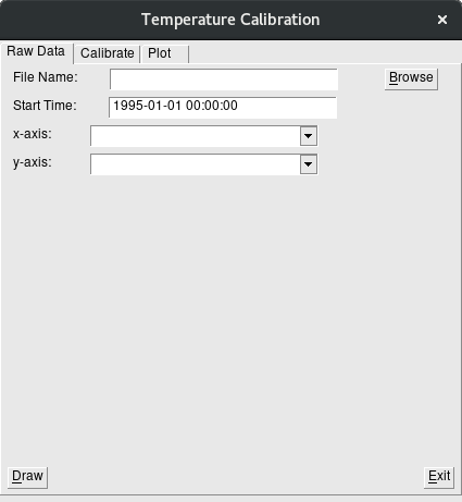
In the first field the name of the RawVoltageOutput-<CryoName>-<DateTime>.dat file needs to be entered are selected via the browse button.
The 'Start Time:' is used to filter out data starting after the time given from the RawVoltageOutput-<CryoName>-<DateTime>.dat file.
The raw data can be plotted (see Draw button) when x-axis and y-axis channels are selected.
Calibrate Tab
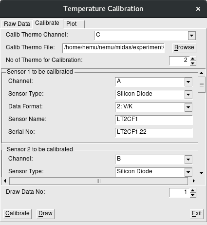
In the top part of this tab, the calibration information needs to be entered, i.e. channel of the calibrated diode (A or B or D1-D5), the LakeShore like calibration table of the calibrated sensor.
The meaning of 'No of Thermo for Calibration' is the number of sensor to be calibrated. Changing this number will change the number of frames in the next section of the 'Calibrate' tab.
It follows the section with frames labelled as 'Sensor X to be calibrated' (X a number). Here the proper channel needs to be selected, the sensor type, the data format, and a sensor name and the serial number needs to be entered. For the to be calibrated diodes the following naming convention should be used:
- Konti cryo: KCxCFy, where 'x' stands for the number of the Konti cryo, and 'y' for the cold finger 1 or 2, e.g. KC1CF2 means Konti-1 cold finger 2 diode.
- LowTemp cryo: LTxCFy
- Any other diode: try to keep the name cut down to less than 8 characters since otherwise they will be truncated in the LS336.
The buttons at the bottom have the following meaning:
- Calibrate: Will do the calibration (a RawVoltageOutput.dat file in the 'Raw Data' tab needs to be selected!!) and will generate LakeShore like calibration files with names 'Sensor Name'.340, e.g. LT2CF1.340. The file is written in the directory of the selected calibrated sensor.
- Draw: Will plot a curve 'averaged sensor data' versus 'averaged temperature' including error bars given by the standard deviation of the measured values of the RawVoltageOutput.dat file. It is there for checking if something went wrong when taking data.
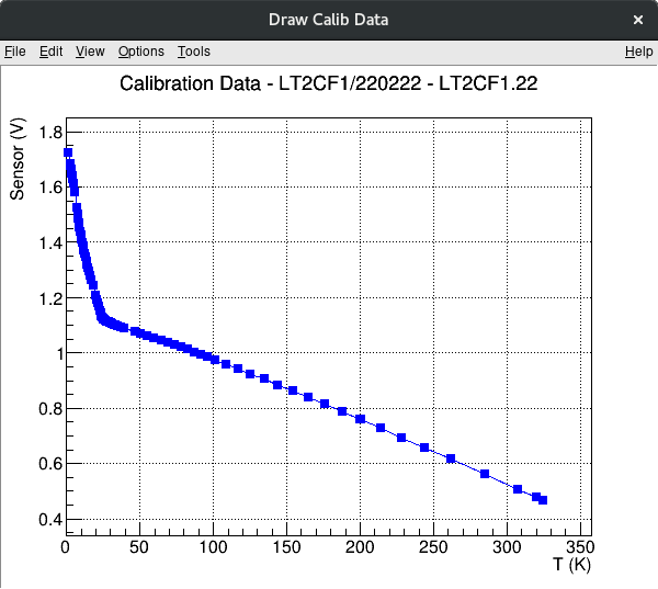
Plot Tab
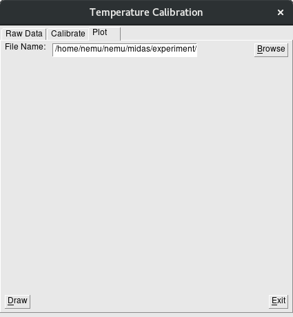
This tab allows to plot LakeShore like calibration files, an example is shown in the above figure. A file name of the calibration file needs to be given, e.g. LT2CF1.340, then the plot will be generated when pressing the Draw button.
talk_rs232
Let's start with the calibration table upload feature of talk_rs232. The program is started from the commandline by talk_rs232 -t <terminalserver> -p <portnumber> , where the terminal-server is probably psts05 or psts06 and the port-number the port to which the LS336 is connected. For example, in WMHA use the following command
talk_rs232 -t psts04 -p 4017
Note that before connecting to the port it should be free, so stop the "Sample SC" program from the midas Status page -> Programs. Next, type the name of the *.340 file proceeded by an @, like @D12345.340. The rest is obvious: after selecting the LakeShore device type (218/336/340) the program prompts for the calibration curve number where the calibration should be stored (see table below) and then the work will be done.
talk_rs232 has a number of other features. Instead of a *.340 file it can handle any other file, that is when you type a file name (proceeded by an @) the contents of that file will be transmitted to the port. After each line, the program waits 200 milliseconds for an answer (this 200 milliseconds can be changed by supplying on the commandline the option -w <timeout>, where timeout is given in milliseconds).
The most basic use of talk_rs232 is to send the lines typed on the keyboard directly to the port and wait for a response. For this case the line is not proceeded by an Non-printable characters can be used by typing %##, where ## is the hexadecimal representation or by type <nnn> where nnn is the ten-base representation. Note that as soon as there are non-printable characters on a line, the line will not be appended by a carriage-return line-feed. Those characters have then to be supplied by the user. One can escape <, >, \ and % by proceeded them with backslash. The output received is presented in printable and non-printable characters.
Table of the calibration-curves as stored in the Sample Cryo LakeShore336
| Curve Index | Thermometer Name |
|---|---|
| 21 | KC1CF1 |
| 22 | KC1CF2 |
| 23 | KC2CF1 |
| 24 | KC2CF2 |
| 25 | KC3CF1 |
| 26 | KC3CF2 |
| 27 | KC4CF1 |
| 28 | KC4CF2 |
| 41 | ??LT1CF1?? |
| 42 | ??LT1CF2?? |
| 43 | LT2CF1 |
| 44 | LT2CF2 |
| 60 | Pressure040306 |
Technical Details concerning the calibration procedure
-
Where are the programs?
The source code for tempCalib is found under$HOME/nemu_utils/calibration/src.
The source code for talk_rs232 is found under$HOME/nemu_utils/talk_rs232.
The executables are installed$HOME/midas/bin. -
Where are the calibration tables?
The calibration tables are found under$HOME/midas/experiment/nemu/temp_calib_curves. For each LakeShore calibrated diode there is a subdirectory with all the LakeShore provided files. There is also a README file with additional information. -
Structure of the RawVoltageOutput.dat file
The RawVoltageOutput.dat is generated by theDUMP-command of lemAutoRun, hence check lemAutoRun/DUMP. -
Structure of the LakeShore 340-file
The structure is pretty much self-explanatory and hence only a code snippet is given here:
 Sensor Model: KC1CF1/060224

 Serial Number: D71714

 Data Format: 2 (Volts/Kelvin)

 SetPoint Limit: 325.0 (Kelvin)

 Temperature coefficient: 1 (Negative)

 Number of Breakpoints: 125


 No. Units Temperature (K)


 1 0.46480 325.000

 2 0.51892 302.220

 3 0.54409 291.625

 4 0.56833 281.445

 5 0.59168 271.607

 6 0.61394 262.208

 7 0.63575 252.955

 8 0.65654 244.109

 9 0.67652 235.577

 10 0.69572 227.336