ChannelAssignment - FAQ
Nemu Slowcontrol System
- Introduction
- Nemu Slow Control Overview
- Integration of the MIDAS Slow Control Device Drivers
- General Structure of a Device Driver
- List of the device drivers (DD) used in the LE-uSR experiment
- Nemu MIDAS Event ID's List
- MIDAS Slowcontrol Bus (MSCB)
- NEMU Graphical User Interface Programs (GUI)
Introduction
This is the documentation for the low energy muon spin rotation experiment (  ) slow control system. The slow control system is based on MIDAS (http://midas.psi.ch or http://midas.triumf.ca) which is a data acquisition system under the GPL which is used in particle and nuclear experiments. Since the main structure of ALL the DD is pretty much the same, first the general structure of the DD and their integration into MIDAS is going to be described.
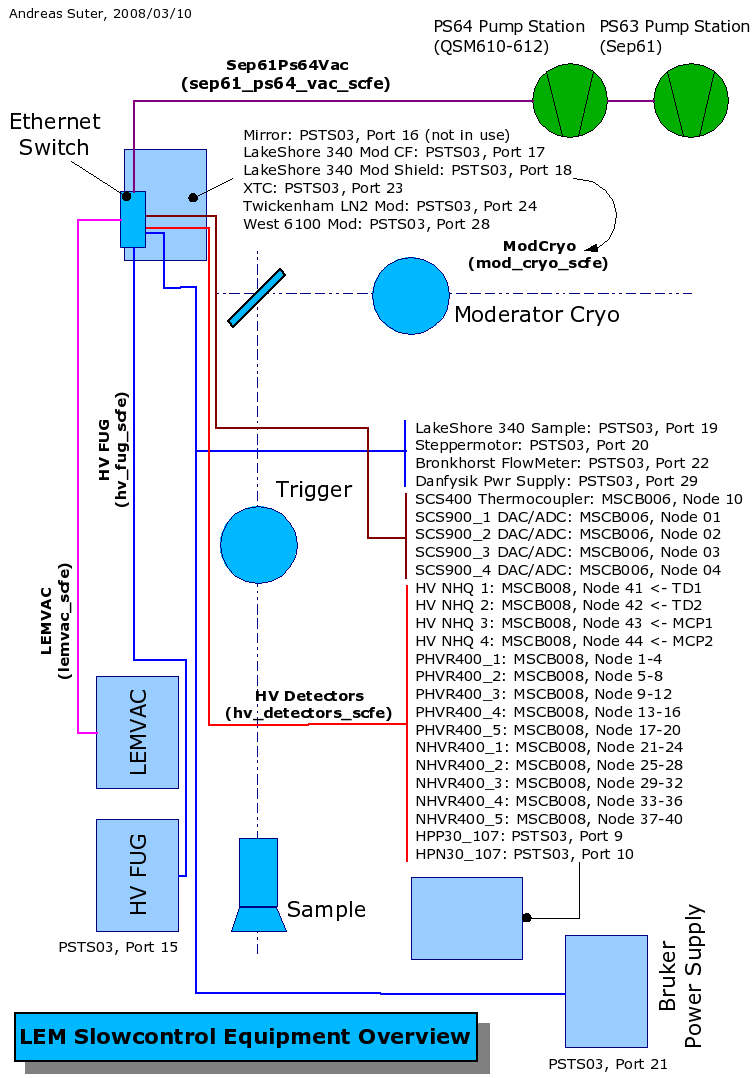
Nemu Slow Control Overview
Before going into the details of the MIDAS Slow Control System, here an overview of the current experimental slowcontrol equipment.
Integration of the MIDAS Slow Control Device Drivers
The slow control system is part of MIDAS. It handles equipment to monitor the general environment of the experiment like pressure, temperature, high voltages, etc. All these parameters are cyclically read and the values are stored in the online database (ODB). A nice history system allows to display these data, so that one can follow the time evolution off all or part of these parameters. It is called slow control system, since the cyclical readout is typically done on a 1 minute base. Though, as will be described, the polling of the individual devices is done more often, and in case the values change significantly, the ODB is updated much faster. For details we refer the reader to the MIDAS documentation.
The slow control system consists of different types/layers of drivers, namely
- slow control frontend
- class driver
- device driver (DD)
- bus driver
The slow control frontend is a collection of DD bound to a logical unit which e.g. will show as an entry point in the web-interface. In the slow control frontend the class drivers, device drivers and bus drivers are linked to each other, the update rate is defined and some additional flags are defined (details see the MIDAS docu and/or the source).
The class driver is an abstract driver which handles the interfacing of the device driver to the ODB and also is responsable for the time handling. At the moment there are 3 class drivers available:
- high voltage class driver
- multi class driver
- generic class driver
Each of them is specialized for a specific target group of device drivers.
The device driver is the driver which handles the communication with a specific device on command level.
The bus driver is a low level driver which is handling the actual communication between the computer and the device on protocol level, e.g. tcp/ip, rs232, ...
The hierarchical structure is
MIDAS, ODB <-> slow control frontend <-> class driver <-> device driver <-> bus driver <-> device
General Structure of a Device Driver
In this section a very brief description of the general structure of a device driver shall be given. For a more extensive discussion see e.g. the home page of MIDAS (http://midas.psi.ch or http://midas.triumf.ca).
Every DD has an entry function which looks something like:
INT bruker(INT cmd, ...)
{
va_list argptr;
HNDLE   hKey;
INT     channel, status;
float   value, *pvalue;
void    *info, *bd;
char    *name;
DWORD   flags;
va_start(argptr, cmd); status = FE_SUCCESS;
  switch (cmd) {
    case CMD_INIT:
      hKey = va_arg(argptr, HNDLE);
      info = va_arg(argptr, void *);
      channel = va_arg(argptr, INT);
      flags = va_arg(argptr, DWORD);
      bd = va_arg(argptr, void *);
      status = bruker_init(hKey, info, channel, bd);
      break;
case CMD_EXIT:
info = va_arg(argptr, void *);
status = bruker_exit(info);
break; case CMD_GET:
info = va_arg(argptr, void *);
channel = va_arg(argptr, INT);
pvalue = va_arg(argptr, float*);
status = bruker_get(info, channel, pvalue);
break; case CMD_GET_DEFAULT_NAME:
info = va_arg(argptr, void *);
channel = va_arg(argptr, INT);
name = va_arg(argptr, char *);
status = bruker_get_default_name(info, channel, name);
break; case CMD_SET:
info = va_arg(argptr, void *);
channel = va_arg(argptr, INT);
value = (float) va_arg(argptr, double);
status = bruker_set(info, channel, value);
break; default:
break;
}va_end(argptr);
  return status;
}
The connection between the class driver and the DD is done via a set of command tags. There are different sets of command tags, depending on the class driver. Before describing the command tags in more detail, a list of these tags for the different class drivers is presented.
| generic | multi | hv | comment |
| CMD_INIT | CMD_INIT | CMD_INIT | initialize DD tag |
| CMD_EXIT | CMD_EXIT | CMD_EXIT | terminate DD tag |
| CMD_GET_DEFAULT_NAME | CMD_GET_DEFAULT_NAME | CMD_GET_DEFAULT_NAME | get default names DD tag |
| CMD_GET | CMD_GET | CMD_GET | get DD tag |
| CMD_SET | CMD_SET | CMD_SET | set DD tag |
| CMD_SET_LABEL | CMD_SET_LABEL | CMD_SET_LABEL | set label DD tag |
| CMD_GET_DEMAND (gerneric, hv) | X | CMD_GET_DEMAND (gerneric, hv) | get demand DD tag |
| CMD_GET_DEFAULT_THRESHOLD (gerneric) | X | X | get default threshold DD tag |
| X | X | CMD_GET_ALL (hv) | get all DD tag |
| X | X | CMD_GET_CURRENT (hv) | get current DD tag |
| X | X | CMD_GET_CURRENT_ALL (hv) | get current all DD tag |
| X | X | CMD_SET_ALL (hv) | set all DD tag |
| X | X | CMD_SET_CURRENT_LIMIT (hv) | set current limit DD tag |
| X | X | CMD_SET_CURRENT_LIMIT_ALL (hv) | set current limit all DD tag |
CMD_INIT
<p>Linked to this tag, an initializing routine of the DD is called. This init routine
   has the following purpose:

   -# It allocates the memory for the DD info structure and initialize it.
   -# If the DD specifc structure are not present in the ODB yet, generates
      these entries.
   -# Establish the connection to the <b>bus driver</b>.
   -# Checks the status of the device.
CMD_EXIT
<p>Linked to this tag, an exit routine of the DD is called. This exit routine
   has the following purpose:

   -# It free's the memory of the DD info structure.
   -# It terminates the connection to the <b>bus driver</b>.
CMD_GET_DEFAULT_NAME
 <p>Linked to this tag, a routine of the DD is called. This routine
    has the following purpose: At startup this routine is called and allows to send
    the <b>class driver</b> default names for the labels in the ODB of the different chanels.
CMD_GET
<p>Linked to this tag, an get routine of the DD is called. This get routine
   has the following purpose: It reads a measured value from the device with the help of
   the <b>bus driver</b>. The <b>bus driver</b> binding is done via macros (which is not
   the most beautiful approach.)
CMD_SET
<p>Linked to this tag, an set routine of the DD is called. This set routine
   has the following purpose: It sends a demand value to the device with the help of
   the <b>bus driver</b>. The <b>bus driver</b> binding is done via macros (which is
   not the most beautiful approach.)
CMD_SET_LABEL
<p>Linked to this tag, an set label routine of the DD is called. <em>Have no idea
   what the meaning of this label is. It is not used in any of our DD.</em>
CMD_GET_DEMAND (gerneric, hv)
<p>Linked to this tag, an get demand routine of the DD is called. This get demand routine
   has the following purpose: It reads the demand value from the device back, this with
   the help of the <b>bus driver</b>. The <b>bus driver</b> binding is done via macros
   (which is not the most beautiful approach.)
CMD_GET_DEFAULT_THRESHOLD (gerneric)
<p><em>This command tag is not used in any of our DD.</em>
CMD_GET_ALL (hv)
<p>Linked to this tag is a routine which reads back all the high voltage values
   of all the channels of the HV device.
CMD_GET_CURRENT (hv)
<p>Linked to this tag is a routine which reads back all the measured current value
   of a specific channel of the HV device.
CMD_GET_CURRENT_ALL (hv)
<p>Linked to this tag is a routine which reads back all the measured current values
   of all the channels of the HV device.
CMD_SET_ALL (hv)
<p>Linked to this tag is a routine which sets all the demand high voltage values
   of all the channels of the HV device.
CMD_SET_CURRENT_LIMIT (hv)
<p>Linked to this tag is a routine which sets the current limit
   of a specific channel of the HV device.
CMD_SET_CURRENT_LIMIT_ALL (hv)
<p>Linked to this tag is a routine which sets the current limits
   of all the channels of the HV device.
List of the device drivers (DD) used in the LE-uSR experiment
- \ref bronkhorst (bronkhorst.h, bronkhorst.c)
- \ref bruker (bruker.h, bruker.c)
- \ref fug (hv_fug.h, hv_fug.c)
- \ref nhq (hv_nhq_20xm_mscb.h, hv_nhq_20xm_mscb.c)
- \ref hvr400 (hvr400.h, hvr400.c)
- \ref hpx30_107 (hpx30_107.h, hpx30_107.c)
- \ref ls340 (LakeShore340.h, LakeShore340.c)
- \ref lemvacDD (lemvac.h, lemvac.c)
- \ref mirror (mirror.h, mirror.c)
- \ref ps64 (ps64.h, ps64.c)
- \ref scs400DD (scs400.h, scs400.c)
- \ref scs900DD (scs900.h, scs900.c)
- \ref sep61vac (sep61vac.h, sep61vac.c)
- \ref twickenham (twickenham.h, twickenham.c)
- \ref west6100 (west6100.h, west6100.c)
- \ref xtc (xtc.h, xtc.c)
Bronkhorst Mass Flow Meter
<p>The bronkhorst mass flow meter for He gas is used together with the
   'Konti-Cryos' (temperature range 4.5K - 300K) and the 'Low-Temp-Cryo' (temperature
   range 2K - 300K). For the 'Konti-Cryos' it is placed between the cryo and the
   alcatel try pump and is regulating the He gas flow (for details regarding the
   operatrion of the bronkhorst flow meter see the operation manual for the 'Konti-Cryos').
   In case of the 'Low-Temp-Cryo' the bronkhorst is regulating the He gas flow at
   the phase separator.
Bruker Power Supply
<p>The bruker power supply (0..500A, max. 75V) is used as the current source for the
   electromagnets generating the magnetic field for TF-uSR experiments.
High Voltage FUG's
<p>The FUG's are the high volatge source for the low energy muon beamline (tertiary
   beamline). There are at the moment 12 such HV devices with different maximal high voltage.
   Since these devices have only an analog inputs to control the high voltage and the
   current limit, an additional hardware interface is used, in order to enable a computer
   controlled operation. This hardware interface consists of field point modules from
   'National Instruments'.
Detector High Voltage Devices: NHQ
<p>Precision NIM High Voltage Supply NHQ STANDARD. Used as a high voltage source for the
   trigger detector, the MCP1 and the MCP2. Since the NHQ's are good hardware, but having
   a very crappy software interface, there is a scs210 interface between the midas control
   system and the NHQ's. Only by this trick the NHQ's can be used within a network.
MSCB HVR400 High Voltage Modules
<p>The MSCB HVR400 are 4 channel active high voltage dividers. They need an external
feeding. Each channel can than set to its specific voltage (of course lower than the
applied feeding). The voltage is ranging from 0-2800V. In the LEM experiment they are
used as the source of the PM's.
Detector High Voltage Devices: HPX30_107
<p>The HPX30_107 from iSeg are single channel high voltage devices which can drive a
current up to 100mA. They are used as the main feeds for the HVR400.
Keithley 2700 Multimeter
<p>The Keithley 2700 multimeter, including a 7700 scanner card, is misused for
   multiple purposes. It is measuring the valve positions of the UHV system of the
   apparatus, measuring the LN2 level of the 'DeMaCo' LN2 system, measuring the current
   sent through the electromagnet via zero flux meter, monitors thermoelements, ...
LakeShore Temperature Controller (Type 340)
<p>The temperature controller are used to monitor and control the temperature of
   the sample cryostates as well as to monitor the temperature of the moderation
   cryostate.
Vacuum Control Interface
<p>The vacuum controller device driver (lemvac) handles the communication between the
   Nemu Siemens SPS vacuum control unit and MIDAS.
   There is a Qt GUI (\ref lemvac) available which presents the informations in an user
   friendly way.
Neocera LTC-21 Temperature Controller
<p>We use this temperature controller for our moderation cryostat. It is mainly used
   as a monitor device.
Mirror Controller
<p>The mirror controller can change/read the angular setting of the mirror of the
   tertiary beamline. The mirror is used to separate the low energy muons from the high
   energy ones. The mirror controller is a home build <em>MONSTER</em> with an RS232
   interface programmed in some BASIC dialect, which is slow and errorsome.
SPS Pump Controller for PS64 (QSM610-612)
<p>The PS64 is the DD handling the communication between the PS64 SPS pumping control
unit and midas. The PS64 is the pumping station of the last quadrupol triplet (QSM610-612)
of the secondary beamline in muE4.
MSCB SCS400 Thermo Coupler Card
<p>8 channel thermo coupler card with digital output to control a power thyristor box.
MSCB SCS900 ADC/DAC Card
<p>8 cannel ADC/DAC card. ADC channels -10 to 10V, 16 bit. DAC -10 to 10V, 12bit.
SPS Pump Controller for PS63 (Sep61)
<p>The Sep61vac is the DD handling the communication between the PS63 SPS pumping control
unit and midas. The PS63 is the pumping station of the separator Sep61 of the secondary
beamline in muE4.
LN2 Level Meter, Twickenham
<p>The twickenham LN2 level meter is used to monitor the LN2 level in one of our 200l
   LN2 dewars.
Needle Valve Controller 'West 6100' for the moderation cryostat 'Moddy'
<p>The multi purpose PID controller 'West 6100' is used in our experiment as a needle valve
   controller for the moderation cryostate (called 'Moddy'). The needle valve is tuning the amount
   of LHe the cold finger region of Moddy can enter.
Microbalance Controller, XTC
<p>The XTC is a microbalance controller connect to a crystal oscillator which is used
   to measure the deposition rate/thickness of the Van der Waals gases used to grow the
   moderator.
Nemu MIDAS Event ID's List
MIDAS handles events via envent id's (EID). The EID are used to handle the events also in the history system (mlogger).
In order to put some logic into the system we decided that the EID will have the following general structure.
| EID | Purpose |
| <50 | Fast hardware related events |
| >50 | Slow controll related events |
Here is the table of the Nemu experiment EID.
| Name | Event ID | Port Info | Comment |
|---|---|---|---|
| SCS900 | 51 | (1) | |
| SCS400 | 60 | mscb006:(1,10) | |
| SampleCryo | 70 | (2) | |
| ModCryo | 71 | (3) | |
| HV | 72 | psts03:4015 | FUG's |
| HV Detectors | 73 | (4) | |
| Danfysik | 81 | psts03:4029 | |
| Bruker | 82 | psts03:4021 | |
| LEMVAC | 100 | lemvacuum:2000 | |
| beamline | 101 | pc451:10000; pc130:10000; sep61:5000 | |
| Sep61Ps64Vac | 102 | ps64vac:2000; sep61vac:2000 |
| (1) | ||
|---|---|---|
| Name | Port | Comment |
| SCS900_1 | mscb006:(1,1) | (Group, Node) |
| SCS900_2 | mscb006:(1,2) | |
| SCS900_3 | mscb006:(1,3) | |
| SCS900_4 | mscb006:(1,4) | |
| (2) | ||
|---|---|---|
| Name | Port | Comment |
| LS340_Sample | psts03:4019 | |
| Bronkhorst | psts03:4022 | |
| (3) | ||
|---|---|---|
| Name | Port | Comment |
| LS340_CF | psts03:4017 | |
| LS340_Shield | psts03:4018 | |
| XTC | psts03:4023 | |
| LN2 | psts03:4024 | Twickenham |
| West6100 | psts03:4028 | |
| (4) | ||
|---|---|---|
| Name | Port | Comment |
| TD1 | mscb008:(1,41) | (Group, Node) NHQ 205M |
| TD2 | mscb008:(1,42) | NHQ 205M |
| MCP1 | mscb008:(1,43) | NHQ 204M |
| MCP2 | mscb008:(1,43) | NHQ 204M |
| PHVR400_1 | mscb008:(400,1) | pos. NHV400 |
| PHVR400_2 | mscb008:(400,5) | |
| PHVR400_3 | mscb008:(400,9) | |
| PHVR400_4 | mscb008:(400,13) | |
| PHVR400_5 | mscb008:(400,17) | |
| NHVR400_1 | mscb008:(400,21) | neg. NHV400 |
| NHVR400_2 | mscb008:(400,25) | |
| NHVR400_3 | mscb008:(400,29) | |
| NHVR400_4 | mscb008:(400,33) | |
| NHVR400_5 | mscb008:(400,37) | |
MIDAS Slowcontrol Bus (MSCB)
The MSCB is development at PSI (http://www.psi.ch/) driven by Stefan Ritt (stefan.ritt@psi.ch) and Reinhard Schmidt (reinhard.schmidt@psi.ch). Their very sparse documentation page is found under http://midas.psi.ch.
This bus is a kind of "poor man's" version of a field bus with less flexibility, but on the other hand it is optimized for experiment environments and much cheaper (typical 20US$ per node). Although this bus is integrated into the MIDAS data acquisition system, it can be used independently from Midas.
The MSCB bus uses the RS-485 standard for commication. This standard is similar to the well-known RS-232, but uses differential signals for superior noise immunity. The bus is controlled from a PC using an parallel port to RS-485 converter. On each bus segment, up to 256 nodes can be connected in parallel. Using one layer of repeaters, 65536 nodes can be operated on a single bus, which makes the MSCB bus suitable for large experiments typically found in high energy physics. The bus protocol uses an addressing scheme to talk to individual nodes. Multi-master operation is possible using a token-ring scheme.
MSCB Devices used in the Nemu Experiment
Here comes the list of the MSCB modules/devices used in the Nemu experiment:
MSCB ethernet submaster
The scs260 is a ethernet interface to the MSCB bus, called sub-master.
MSCB RS232 interface module
The scs210 is a RS232 interface to the MSCB bus.
MSCB Thermo Coupler Card
8 channel thermo coupler card with digital output to control a power thyristor box.
MSCB ADC/DAC card
8 cannel ADC/DAC card. ADC channels -10 to 10V, 16 bit. DAC -10 to 10V, 12bit.
Structure of the MSCB Software on the Computer Side
The whole source code for the MSCB computer side is found under $MIDAS_ROOT/mscb. With the aid of the service program msc the MSCB can be scanned, configured and all available commands can be executed via simple commands. However, the msc must not be used in parallel with a running slowcontrol frontend process, since this is leading to bus communication errors.
To communicate from MIDAS with any MSCB modules, there are two possiblities:
- write a bus driver by using the mscb library (
$MIDAS_ROOT/mscb/mscb.c). This was done for the scs400 and scs900 modules. - using the
mscbbusbus driver from MIDAS. This was done for most other RS232 devices which are connected to the MSCB bus via the scs210.
Structure of the MSCB Software on the Microcontroller Side
At the heart of most MSCB modules we are using is a C8051F12x micro controller from Silicon Laboratories (http://www.silabs.com/). Stefan Ritt has written all the core routines, so that we only needed to adopted in special situations.
There is a set of device independent MSCB routine for the micro controllers. They are collected in the following files:
$MIDAS_ROOT/mscb/embedded/mscbmain.c$MIDAS_ROOT/mscb/embedded/mscbutil.c
These routine manage the communication via the MSCB bus, interpreting the incomming commands, interrupt handling, etc.
A specfic device is embedded into these routines via a generic set of routines. They consist of the following routines:
user_initinitialize the deviceuser_writeinterrupt routine which is called when the computer likes to write to the device. Since this is an interrupt routine, usually only a few flags are set, in order not to block the bus. Theuser_loopis than handling the necessary operations.user_readreads data from the device (if there is any).user_funcdon't now!user_loopis the main routine handling the device specific tasks
NEMU Graphical User Interface Programs (GUI)
To be written yet ...
High Voltage Editor (hvEdit)
see hvEditVacuum Control Unit GUI (lemvac)
To be written yet ...
NEMU Backout GUI (lemBackout)
To be written yet ...
Moderation Cryo Control GUI (lemModCryo)
To be written yet ...
LEM Beamline Control GUI
based on Root, not on Qt, similar functionality as SetPoint, but is integrated in a MIDAS experiment; connects as a MIDAS client to a MIDAS experiment, gets and sets beamline magnets by changing ODB settings (which are then sent by the beamline device driver), can read and write .set files, to be continued...
ChannelAssignment - main